

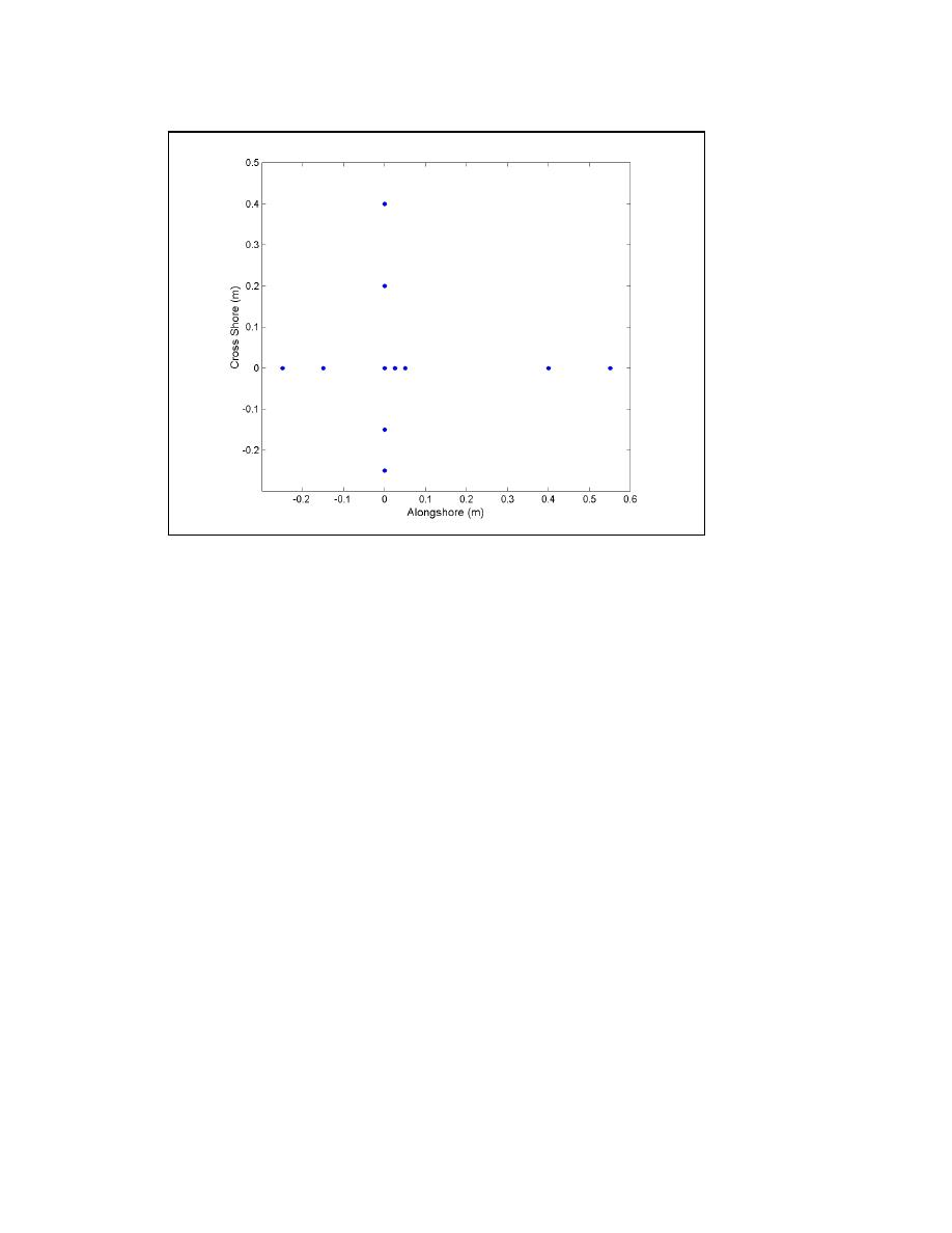
Figure 25. 0.8- by 0.8-m-aperture cross-shaped pixel sampling array orientation
and pixel sensor spacing
For Structure 1, the two camera views overlap slightly resulting in 20
collocated CIIS arrays. The combination of the two views results in 82 video-
based directional measurement locations. The Structure 2 experiment
arrangement required four camera views to cover the measurement area of
interest. Arrays are regularly spaced in a 0.3-m grid. Edges of the camera views
overlap slightly, resulting in 72 collocated CIIS arrays. Combination of the
Structure 2 camera views produces 481 video-based directional measurement
locations. For the Structure 3 and 4 arrangements, a single camera view was
required to observe the measurement area. Arrays are regularly spaced at 0.3-m
intervals, giving 305 measurement locations. Sampling elements are located on
only one-half of the diffraction region, because it is assumed that diffraction
patterns are symmetric in the bay for this model configuration.
Image processing
Recorded video of the wave experiment is played back to the image
processor for digitization. The platform for the image processing software is a
be defined by the CIIS sampling rate of 30 Hz is 15 Hz. Frequency content
above 15 Hz in the original signal will be aliased or "folded" into the frequency
range between 0 and 15 Hz. Because the high-frequency limits of the target
spectra were sufficiently lower (<70 percent) than the band limiting frequency,
38
Chapter 5 Video-Based Wave Direction Measurement

 Previous Page
