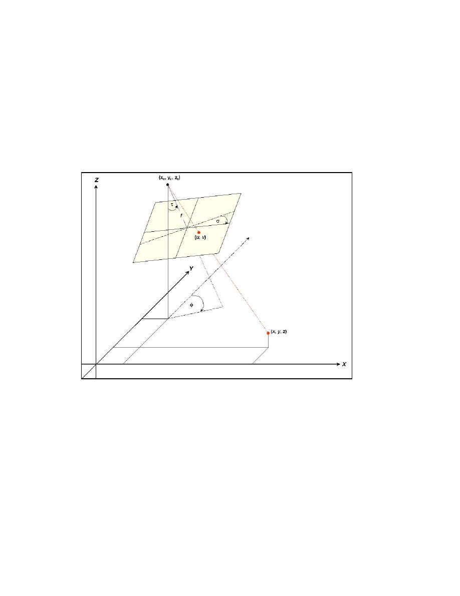
camera locations, and ground control coordinates are measured to establish a
geometric model relating phenomena observed in two-dimensional (2-D) image
coordinates (u,v) to the physical model's three-dimensional (3-D) x-, y-, z-
coordinate system via a direct linear transformation. Figure 19 shows the
geometric relationship between an object observed in image space and in object
space. The capability to transform accurately between image and object space
enables the CIIS to operate as a measurement system. Holland et al. (1997) gives
a comprehensive treatise on the mathematics of the camera calibration (lens
distortion correction) and application of photogrammetric methods.
Figure 19. Geometric relationship between the camera (xc, yc, zc), the object of
interest observed on the image plane (u, v) and in real-world
coordinates (x, y, z), angles of camera rotation (τ,σ,φ), and the
camera focal length (f) (after Holland et al. 1997)
The general premise for video-based wave direction measurement in the
physical model is as follows. Diffuse lamps create a directional gradient of light
over the model. As waves propagate by a fixed point on the free surface, the
intensity of directional specular reflection from the surface of the wave slope
varies from light to dark. The degree of variation depends on the viewing angle
relative to the direction of wave propagation and illumination. A vertical camera
angle observes a field of high- and low-intensity bands over the free surface as
waves propagate toward the source illumination. That is, the forward face of the
wave has a higher intensity signature than the back face of the wave shadowed by
the front. These temporal and spatial variations in light intensity are observed by
a camera and recorded on videotape. The signals are digitized and analyzed to
32
Chapter 5 Video-Based Wave Direction Measurement


 Previous Page
