

J.L. Hench et al. / Continental Shelf Research 22 (2002) 26152631
2619
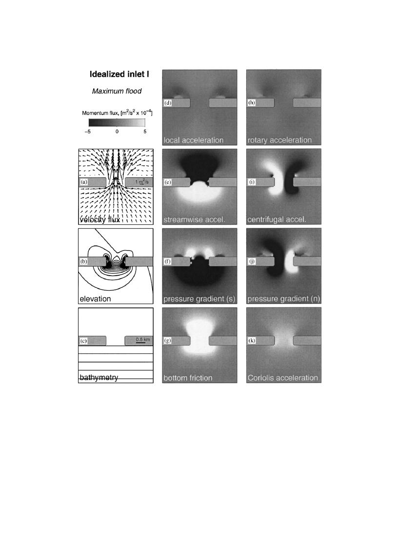
Fig. 2. Circulation and momentum balances for idealized inlet I at maximum flood: (a) velocity flux, the depth-averaged velocity
multiplied by total water column (velocity vectors have been interpolated to a coarser grid with 250 m spacing for clarity); (b) free
surface elevation with 0.5 cm contour intervals; (c) bathymetry with 0.2 m contour intervals; (dk) shaded contours of individual
momentum flux terms (see text for description). The middle column of subplots contains the streamwise momentum terms, the
rightmost column contains normal direction momentum terms.
adjacent to the headlands are much stronger than
(Figs. 4d and h). Near the headlands, streamwise
in the center of the inlet (Fig. 4a). The transient
direction balances are primarily between the
eddies that were so pronounced in the sound for
streamwise acceleration and pressure gradient
inlet I are not present here, and the corresponding
(Figs. 4e and f). Bottom friction is important near
local acceleration terms in this area are small
the headlands as well (Fig. 4g); the spatial pattern

 Previous Page
