2626
COASTAL ENGINEERING 2004
0.15
0.10
0.05
0.00
Phase
-0.05
0
π/2
-0.10
π
3π/2
ξ=6
-0.15
0.0
0.2
0.4
0.6
0.8
1.0
Alongshore Distance (x/B)
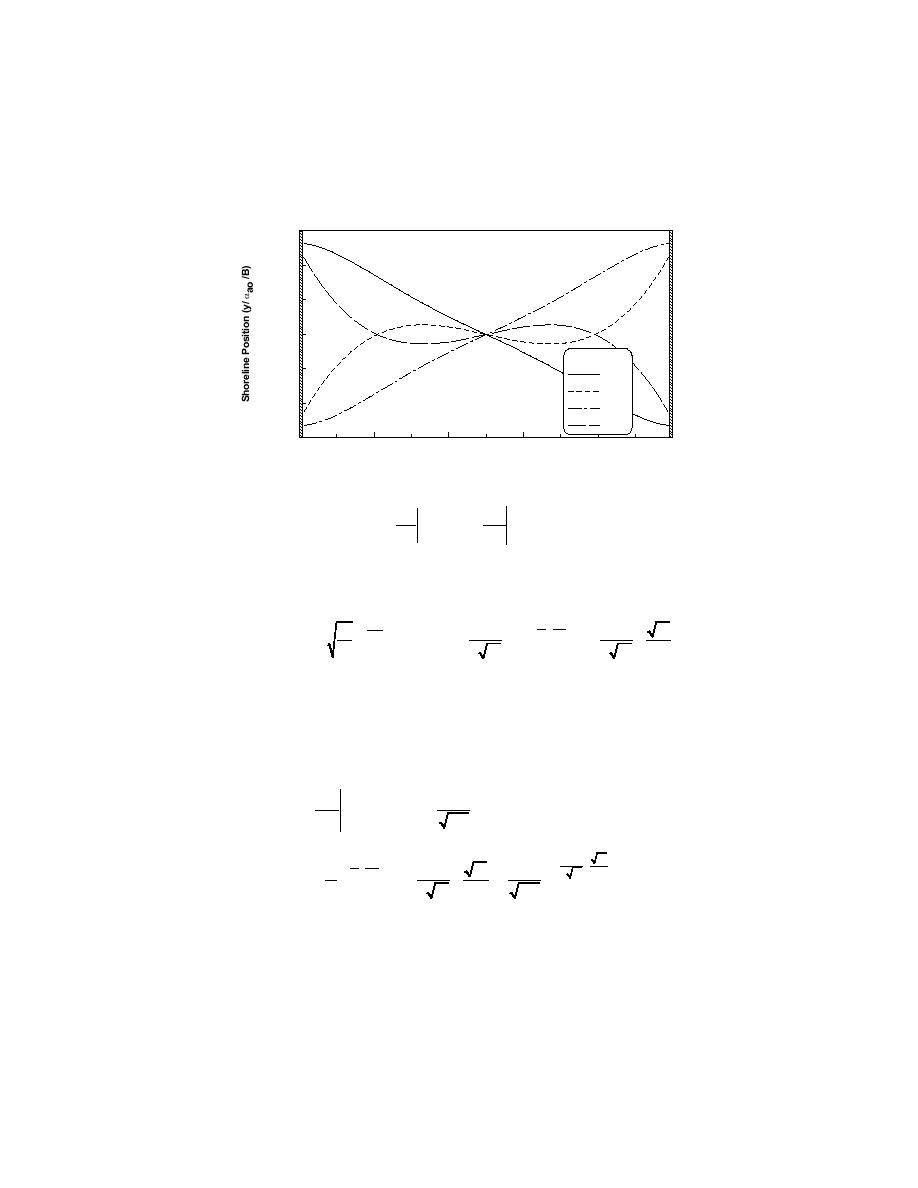
Figure 3. Shoreline evolution in enclosed groin compartment at steady-state conditions when
breaking-wave angle varies sinusoidally with time for ζ = 6.
∂Q
∂2 y
= -R
= 2RQo 2
(13)
Qoff
∂x
∂x
x=0
x=0
where R is a dimensional coefficient [m]. If the wave crests make a constant
angle -αo with the x-axis, giving rise to a longshore transport in the negative x-
direction, the solution describing the accumulation on the updrift side becomes,
⎡ ε t - x2
x εt
ε t ⎞⎤
⎛ x
⎛ x ⎞
+
(
) ⎜
⎢2
⎟⎥
y(x, t) = -α0
R R2 erfc
4εt - R + x erfc
⎟ + Re
+
⎜
e
⎜ 2 εt
R ⎟⎥
⎢ π
⎝ 2 εt ⎠
⎝
⎠⎦
⎣
(14)
A non-dimensional plot of this shoreline evolution is shown in Figure 4
where the solution for R = 0.5 (saying that half of the transport rate approaching
the groin is redirected into the rip) is shown and compared to the case R = 0, i.e.
no offshore rip transport. Based on Eq. (13), the offshore transport Qoff next to
the groin becomes:
∂2 y
⎡ 1
2
e- x / 4εt +
= -2RQoα0 ⎢
Qoff = 2RQo
∂x2
⎣ πε t
x=0
⎤
2
⎛ x
⎞
εt
⎛ x εt ⎞
-⎜
+
⎛ x
εt ⎞
⎟
⎥
⎜ R+ 2 ⎟
1
1
⎜ 2 εt
⎟
R
e⎝ R ⎠
e ⎝
⎠
+
+
⎟-
erfc ⎜
(15)
⎥
⎜ 2 εt
R ⎟
πε t
R
⎝
⎠
⎥
⎦


 Previous Page
