COASTAL ENGINEERING 2004
2627
2.5
ε__
_t
No rip (R = 0)
t =
Rip (R= 0.5)
L2
2.0
1.5
t' =
4.0
3.0
1.0
2.0
1.0
0.5
0.0
0.0
1.0
2.0
3.0
4.0
5.0
Alongshore Distance (x/L)
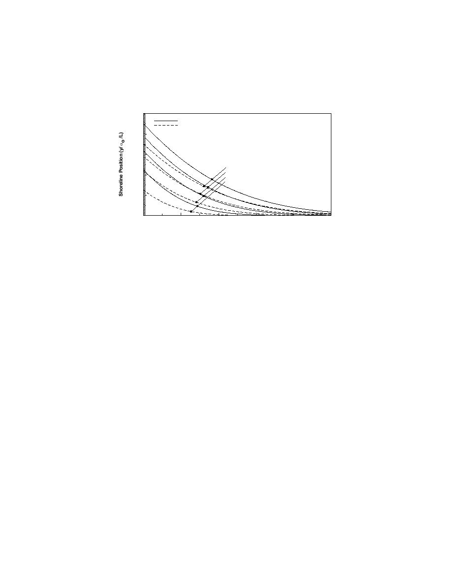
Figure 4. Shoreline evolution updrift of a groin with and without offshore loss in rip current (αo =
11.5 deg).
Figure 5 shows that the relative offshore transport rate Qoff/Qoff,init, where
Qoff,init is Qoff at t = 0, decreases to about 25% of the initial value after about a
dimensionless time t' = 5.5, where t' = εt/L2, and L is a characteristic length, in
this case preferably set to the groin length GL. This result is independent of Qo
and αo. Thus, to take benefit of the reduced offshore loss rates following
shoreline reorientation, wave direction should not change more frequently than
what corresponds to εt/L2 = 5.5, leading to t = 2.75 GL2 D/Qo. This time t may
be regarded as a relaxation time for the system.
If this duration is used as an indicator, for example, with a longshore sand
transport rate amplitude of 500,000 m3/yr, a breaking wave angle of 11.5 deg, a
groin length of 100 m, and a depth of closure of 8 m, the `critical' wave
direction duration is close to 64 days. Thus, if the higher waves come out of the
same overall direction for a longer period than 64 days at this particular location,
there is likely to be longer periods with less offshore losses. On the other hand,
if the with typically changes direction more frequently than this, offshore losses
will be higher.
5.
Numerical Solution of Shoreline Change in a Groin Compartment
including Offshore Losses in Rip Current
Without offshore losses this case is identical to the analytic solution above for a
groin compartment. With an offshore loss included, this case can be considered
as a combination of the two analytic solutions above. However, to solve the


 Previous Page
