January 13, 2004
14:36
WSPC/101-CEJ
00094
537
Progress in Management of Sediment Bypassing at Coastal Inlets
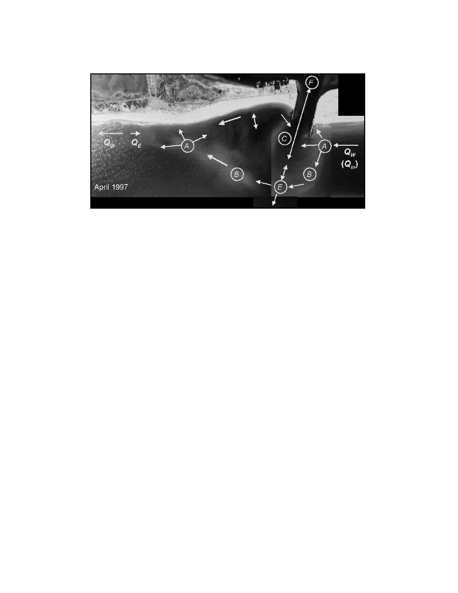
Fig. 2. Interpreted sediment-transport pathways at Shinnecock Inlet.
Figure 2. Interpreted sediment-transport pathways at Shinnecock Inlet.
west beach, as described by Militello and Kraus (2001), which can be consulted for
further information. Here, concepts pertaining to natural bypassing are discussed.
Sediment pathways for Shinnecock Inlet were inferred based on inspection of
the morphology, dredging history, and numerical modeling of the waves and tidal
hydrodynambcShoaillitello and Kraus, 2001). Sediment transport pathways are drawn
Eb i s (M
Qn
in Fig. 2, wheire the attachment bars (A), bypassing bars (B), channel (C ), ebb shoal
(D)Vebb shoal, (E), and flood shBapaseinhoBar, with arrows denoting the interpreted
, Ee
oyl rs s g wn
directions of transport for the situation of predominant (westward) transport. The
(Q ) n
Attachment Bar
total longshore transport rate to the wBsit QW , which serves as the input transport
e
Vi
rate Qin for thEs direction, andBthe rate directed to the east (QAaire annotated on this
QE ) n
V e
figure. Both bar bypQsi)ou,t such as A to B to E to B to A, and tidal(bypassi) g (A
(asE ng
n
VrAbed by Bruun aQd eGch riin sen
b a
to C to F to E) are represented as conceptually desc i e
n
er t
VB
(1959, 1960).
Mathematical details of the Reservoir ModB)oand project studies have been de-
(Q el ut
scribed elsewhere (Kraus, 2000a, 2000b, 2001; Militello andVAraus, 2001; Zarillo,
K
Kraus, and Hoek, 2003), so only its basis and potential applications Qre)ouitscussed
( aA d
here. Figure 3 shows the concept of the model. It requires identification of morpho-
logic features of an inlet, sediment pathways between them (as illustrated in Fig. 2),
and equilibrFigurva3ueConcept featturefo(Kesers,o2r 01l),t whirphologtreaoed lanalogously
ium e l . s of the ske ch s r r rau v i 0in e mo ch are y mt de
to reservoirs. In the model, it is assumed that an individual reservoir can accept and
provide sediment to adjacent reservoirs (morphologic features). The amount pro-
vided to other features is assumed proportional to the amount (volume) of sediment
available and the rate of input. For features with multiple inputs and outgoes, per-
centages among them must be assigned. The model can then calculate the volume
growth of the morphologic features and volumetric rates of natural sand bypassing.
26


 Previous Page
