930
JOURNAL OF PHYSICAL OCEANOGRAPHY
VOLUME 33
lets Research Program (CIRP), ONR (N00014-97-C-
6010), and NSF (OCE-0094938).
APPENDIX
Rotation of xy Momentum Equations into an sn
Coordinate System
The use of a streamwise-normal coordinate system
allows a more intuitive physical interpretation for
strongly curving flow fields. Here we derive a form of
the fully nonlinear transient frictional shallow water
equations by transforming the familiar xy equations.
Here U(x, y, t), V(x, y, t), and (x, y, t) are computed
on a fixed xy grid for all time steps. The elevation and
velocity fields are used to reconstruct each term in the
xy momentum equations at each node in the xy grid.
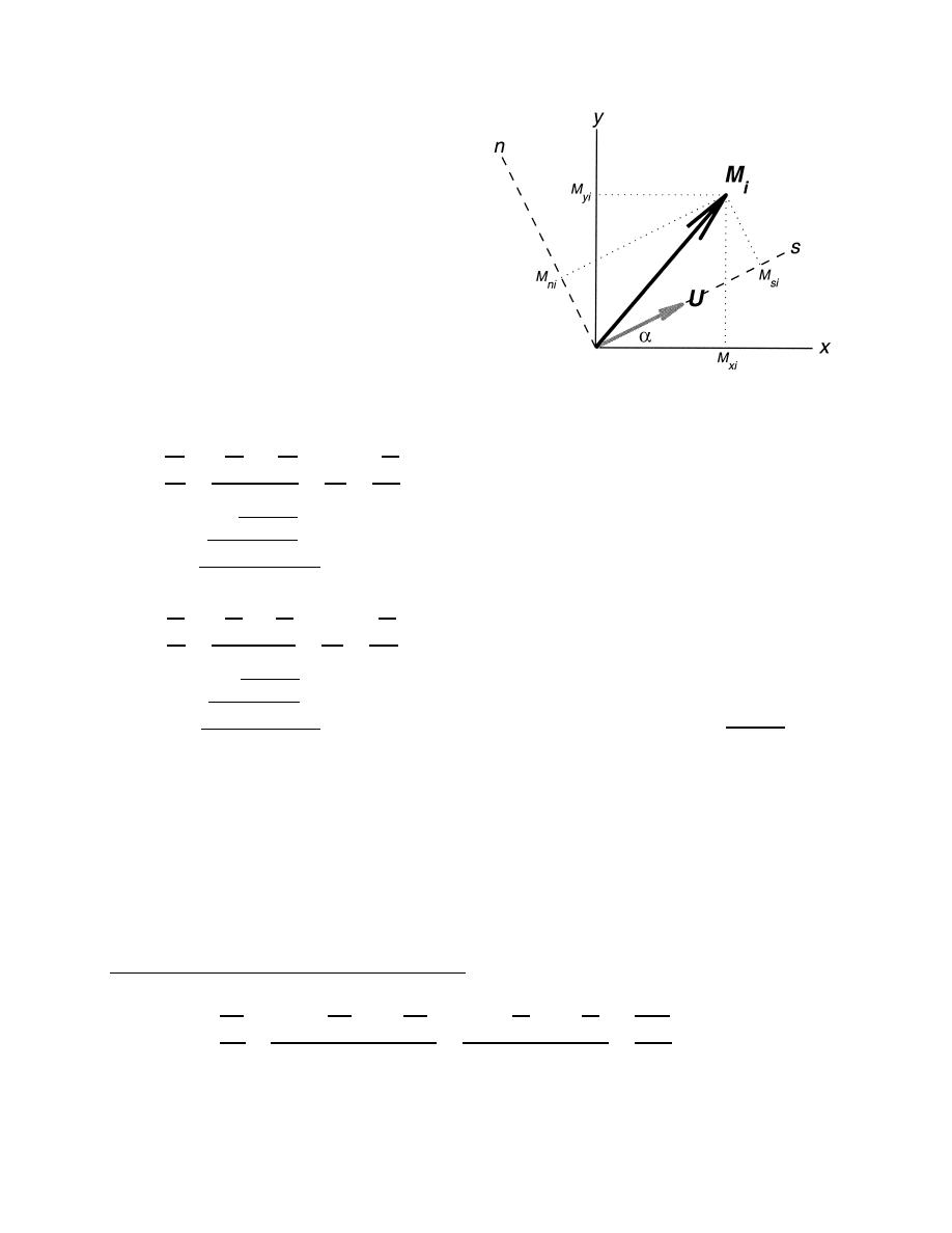
FIG. A1. Coordinate system definition sketch for the xy to sn
transformation. At each time step, an sn coordinate system is es-
Individual xy momentum terms Mxi and Myi are des-
tablished (aligned with the local velocity vector U at each compu-
ignated as
tational node. The local axes rotation angle is (x, y, t). Vector Mi
U
U U
U
represents the ith force or acceleration vector in the momentum equa-
V
fV
g
tions, with xy components Mxi and Myi (e.g., g / x and g / y),
t
x
y
x
and is rotated onto the sn axes to determine local sn components
M
Msi and Mni (e.g., g / s and g / n).
Mx2
Mx3
Mx4
x1
U2
V2
H
Cf
varies so that at all points the alongstream velocity Us
U
0,
(A1)
is equivalent to the speed, and the across-stream velocity
0. From Fig. A1 it should be apparent that mo-
M
Un
mentum terms in sn coordinates are related to those in
x5
the xy coordinate system by
V
U V
V
V
fU
g
Myi sin ,
Mxi cos
Msi
(A3)
t
x
y
y
M
Mxi sin ,
Myi cos
Mni
(A4)
My2
My3
My4
y1
where the index i 1:5 as in Eqs. (A1) and (A2) above.
U2
V2
H
Cf
The sn velocities can be related to the xy velocity
V
0.
(A2)
components using the same orthogonal rotation:
M
V sin
U2
U cos
V 2,
Us
(A5)
y5
U sin
0.
V cos
Un
(A6)
For simplicity, horizontal diffusion terms are omitted
from (A1) and (A2) as they did not contribute signifi-
arctan(V/U ). Equations (A5) and
From Eq. (A6),
cantly to the momentum balances of our inlet simula-
(A6) can also be rearranged to express (U, V ) in terms
tions. At each time step, we define a two-dimensional,
of Us and :
orthogonal, curvilinear coordinate system such that at
Us cos ,
U
(A7)
each grid point, one coordinate direction points in the
streamwise direction (s) and the other points in the
Us sin .
V
(A8)
across-stream or normal direction (n) in the right-hand
sense (see Fig. A1). The orientation of the sn coor-
Substituting the xy momentum terms from (A1) and
dinate system relative to the original fixed xy coordi-
(A2) into (A3) and (A4), and replacing U and V using
nate system, given by the streamline angle (x, y, t),
(A7) and (A8), gives
t
Us
Us
Us
Cf U 2
sin
g cos
sin
0,
Us cos
s
(A9)
x
y
x
y
H
M
Ms2
Ms4
Ms5
s1


 Previous Page
