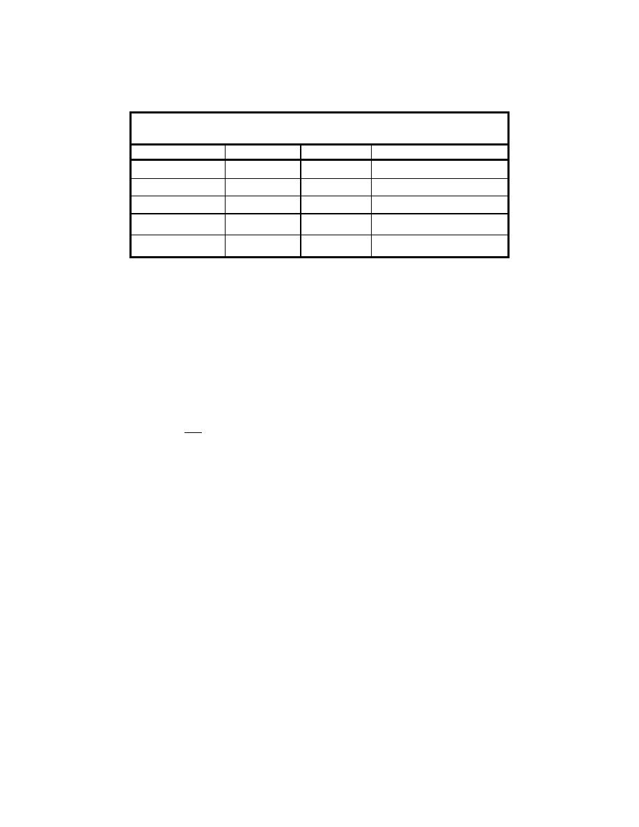
Prototype-to-model scale ratios for horizontal lengths, vertical lengths, flow
velocity, and total discharge are given in Table 4.
Table 4
Distorted Model Froude Scales
Scale
Ratio
Notation
Relationship
Xp / Xm
NX
Horizontal length
Zp / Zm
NZ
Vertical length
NX / NZ
Ω
Model distortion
NV = NZ1/2
Vp / Vm
NV
Velocity
NQ = NX:NZ3/2 = Ω:NZ5/2
Qp / Qm
NQ
Discharge
Model scale was manipulated by specifying appropriate horizontal and
vertical length scales and the discharge scale. Two of the scales can be selected,
and the third is then constrained by the scale equations. For most test series it
was more convenient to keep the flow discharge constant for all experiments and
change the horizontal and vertical dimensions to suit the different model
distortions. This way the flow valve remained at the same setting and difficulties
in adjusting the flow rate to a precise value were avoided.
Solving the discharge scale equation for NZ gives:
2/5
NQ
NZ =
(33)
Ω
For a given distortion, Ω, and a specified discharge scale (usually NQ = 1), the
vertical length scale is determined, and the horizontal length scale is found as:
N X = Ω NZ
(34)
Once the scale ratios were determined, horizontal and vertical dimensions in the
distorted model could be determined based on the prototype target dimensions.
For constant discharge, water depths increased with distortion while the gap
distance decreased.
Velocity measurements
For each test series a velocity measurement grid was established. The grid
encompassed the primary region of interest and included points within the
turbulent and nonturbulent portions of the flow regime. The uniform, rectangular
grid positions were entered into the computer program, which controlled the
traversing system and acquired the data. Grid dimensions established for the
target condition were scaled appropriately for each distorted test so the
39
Chapter 5 Turbulence Scale Effects Experiments


 Previous Page
