

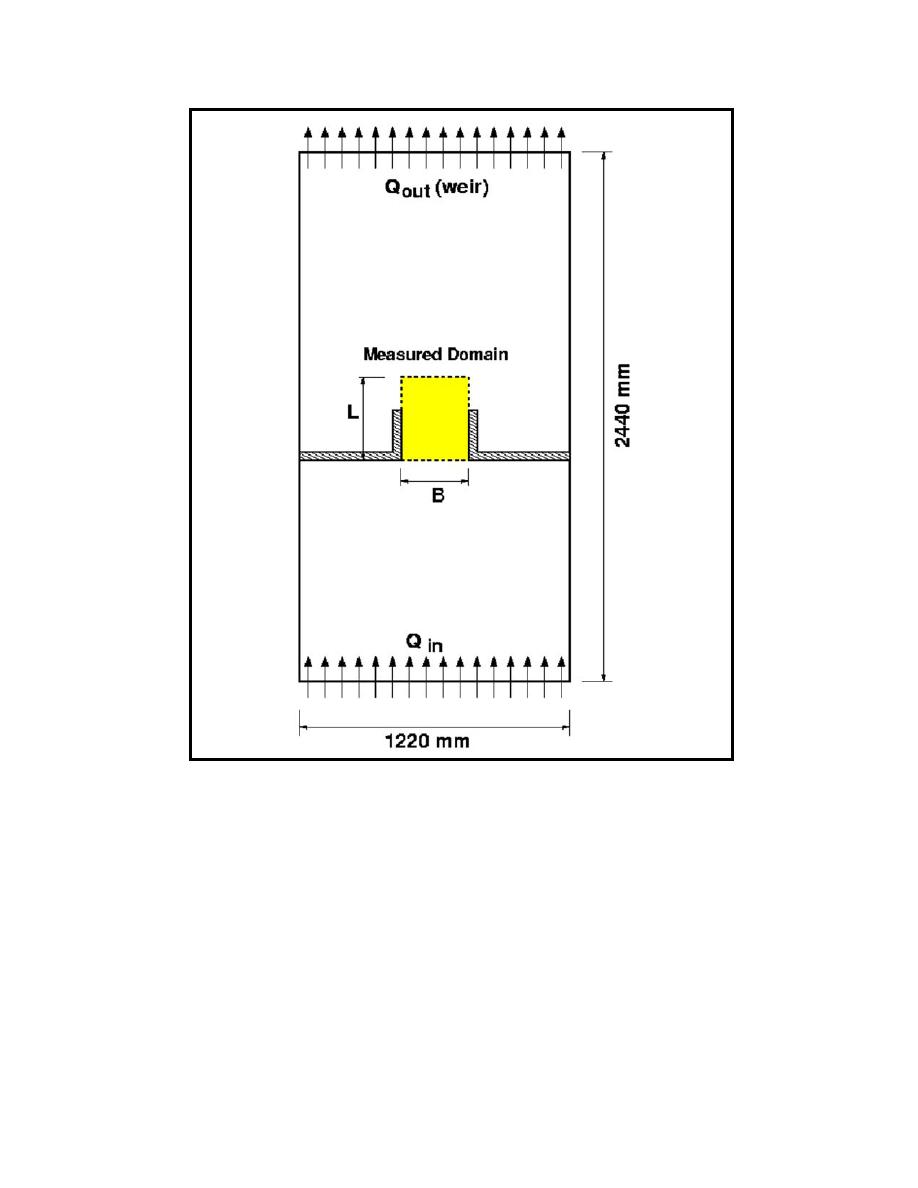
Figure 29. Experiment setup for Case 2 constrained jet flow separation at vertical
edge
Case 2 results
Because Case 2 was similar to Case 1, only a few plots are shown in this
section. Graphical results obtained from the four tests conducted with a
discharge scale of NQ =1.0 were selected as representative of this test
configuration. Complete graphical results for all 12 tests are included in
Appendix B.
Figure 30 compares the prototype velocity vector field with the vectors from
the experiment with distortion of six scaled up to prototype size. The distorted
model results were displaced slightly to the right of the prototype results. Once
again, the comparison between prototype and distorted model was favorable,
although there was some variation evident in the slow-moving flow entrainment
region. Nevertheless, current patterns seemed to be reproduced well in this
50
Chapter 5 Turbulence Scale Effects Experiments

 Previous Page
