

2.0
Location C
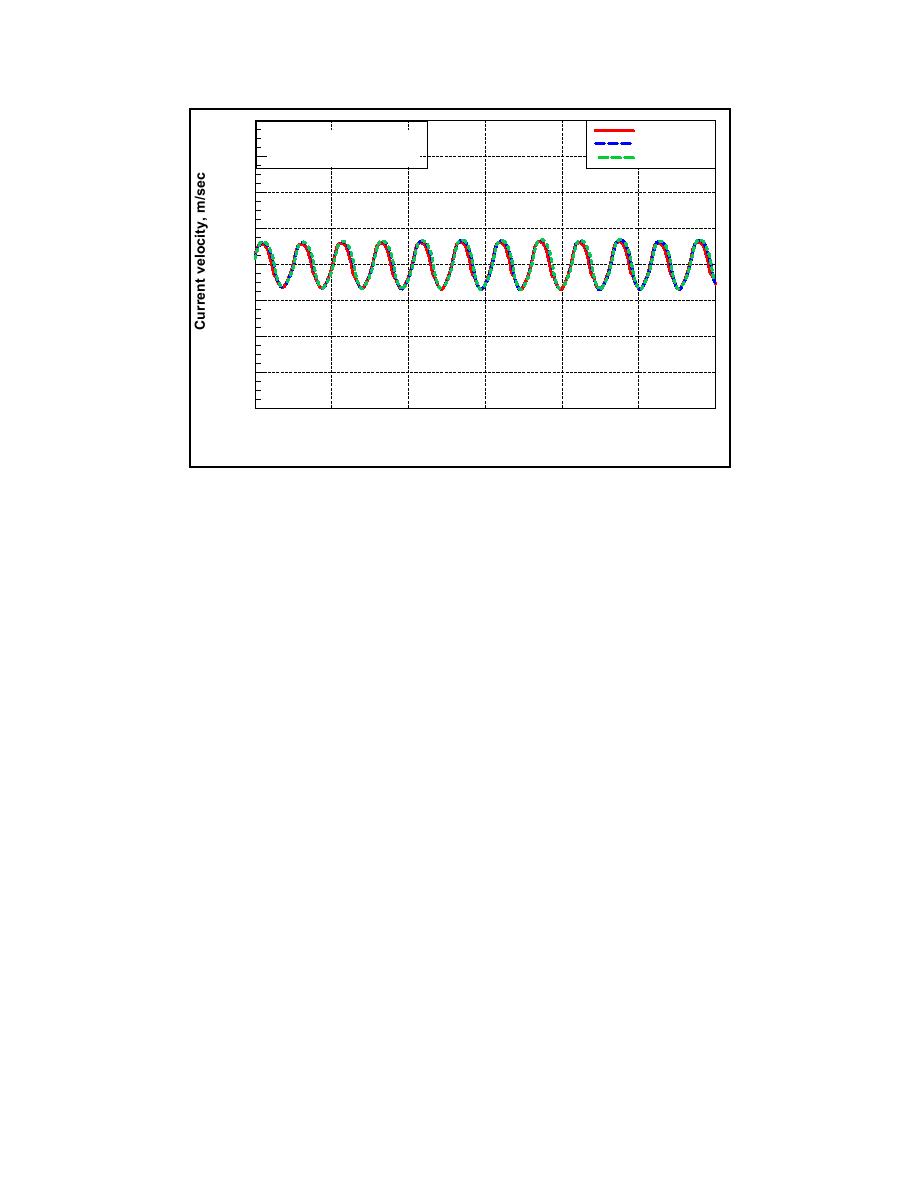
Mattituck Inlet
Location D
and Offshore Shoal Area
1.5
Location E
1.0
0.5
0.0
-0.5
-1.0
-1.5
-2.0
10/9
10/5
10/7
10/8
10/4
10/6
10/3
October 2002 GMT
Figure 5-20b. Current velocity between Mattituck Inlet entrance and offshore
shoal (Locations C through E)
Goldsmith Inlet
Water-surface elevation and current velocity at Goldsmith Inlet and
Goldsmith Pond were calculated with the DYNLET model. DYNLET is well
suited for applications to inlet and bay systems not expected to have complex
horizontal circulation patterns. Goldsmith Inlet is such a system in which flow is
directed primarily along the channel. The implicit solution method of DYNLET
can efficiently calculate for shallow water and strong flows, for which an explicit
solution method would require a small time-step. DYNLET can be considered as
a "1-D plus" model in that it solves for current velocity at specified stations along
each cross section as determined by the depth and bottom friction at each station.
Water level at the nodes and velocity at the stations are calculated, with the
velocity apportioned at the stations according to the bottom friction or
conveyance of the channel (Amein and Kraus 1991).
Model validation
A DYNLET bathymetry grid for Goldsmith Inlet was established as a series
of connected nodes that constitute a channel network originating directly offshore
of Goldsmith Inlet and terminating in the back (southern end) of Goldsmith Pond
(Figure 5-21). The model was forced at Node 1with water-level measurements
adapted from the Mattituck Inlet jetty gauge, and a no-discharge boundary
condition (current velocity of zero) was specified at Node 31 located at the back
of the pond. The distance between nodes was determined so as to represent
significant changes in morphology through consideration of channel or pond
width, depth, and roughness of the bottom. The DYNLET grid of Goldsmith
243
Chapter 5 Circulation Analysis

 Previous Page
