2.0
1.5
T-head
DBW
1.0
0.5
0.0
-0.5
A
B
C
0
2
4
6
8
10
12
14
16
Distance Alongshore (m)
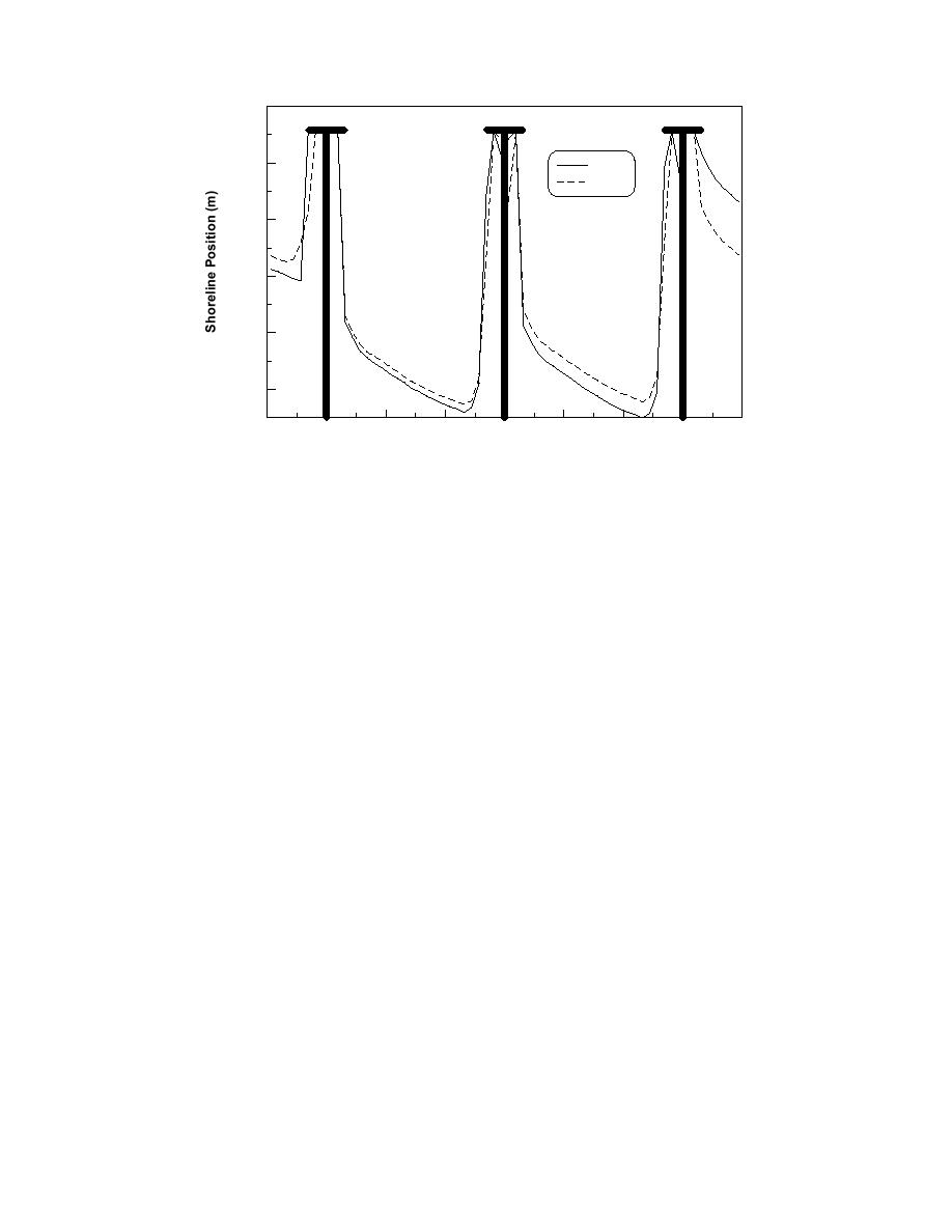
Fig. 10. Comparison of shoreline response inside of T-head groins and DBWs.
CONCLUDING DISCUSSION
This paper has discussed and demonstrated a new capability being
implemented in the GENESIS model. Comparisons with the physical model
experiments of Hashimoto et al. (1981) indicated that the improved algorithm for
representation of T-head groins is working properly.
ACKNOWLEDGMENTS
This paper was prepared as an activity of the Inlet Channels and Adjacent
Shorelines Work Unit of the Coastal Inlets Research Program, U.S. Army Corps
of Engineers (USACE). Permission was granted by Headquarters, USACE, to
publish this information.
REFERENCES
Gravens, M.B., Kraus, N.C., and Hanson, H. 1991. GENESIS: Generalized Model for
Simulating Shoreline Change. Report 2: Workbook and System User's Manual,
Tech. Rep. CERC-89-19, U.S. Army Engineer Waterways Experiment Station,
Vicksburg, MS.
Hanson, H. 1989. GENESIS - A Generalized Shoreline Change Numerical Model, J.
Coastal Research, 5(1): 1-27.
Hanson, H., and Kraus, N.C. 1986. Seawall Boundary Condition in Numerical Models
of Shoreline Evolution. Tech. Rep. CERC-86-3, U.S. Army Engineer Waterways
Experiment Station, Coastal Eng. Res. Center, Vicksburg, MS.
Hanson, H., and Kraus, N.C. 1989. GENESIS: Generalized Model for Simulating
Shoreline Change. Report 1: Technical Reference. Tech. Rep. CERC-89-19, U.S.
Army Engineer Waterways Experiment Station, Vicksburg, MS.
Hanson, H., and Kraus, N.C. 1990. Shoreline Response to a Single Transmissive
Detached Breakwater. Proc. 22nd Coastal Eng. Conf., ASCE, 2034-2046.
11


 Previous Page
